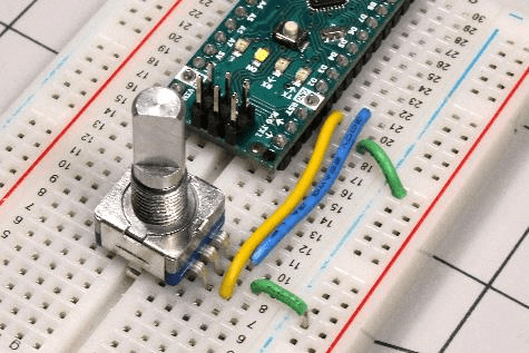
You can control many projects using components like buttons or slider inputs, but what if your build requires a knob? If your project calls for a rotary input, you have two choices: either a potentiometer or a rotary encoder.
Potentiometers, which vary resistance based on the knob position, are simpler and often a solid choice, but you can only turn them clockwise or counter-clockwise (so far). If you need something that can spin continuously in either direction, your best bet is a rotary encoder. If you need help deciding between the two, our encoder vs. potentiometer discussion may help you find your answer.
Encoders come in two basic styles:
1. Incremental encoders use a series of pulses in a quadrature arrangement to indicate how far and in what direction a shaft turns.
2. Absolute encoders inherently know their angular position.
This article will focus primarily on incremental encoders, the type of encoder you’ll see most commonly. Single output encoders (AKA tachometers) are also available, but they are far less useful as they only indicate how far a shaft has moved, not its direction. You can check out our article about types of encoders for a more detailed discussion, but today we’ll cover with the basics of how an incremental encoder works and how to interface it with an Arduino board.
Quadrature Encoders: Tutorial and Overview

Caption: Quadrature diagram for encoder signals A and B. A rising edge for B and a low signal for A signifies moving to the right on this pattern, while a falling edge for A with B high signifies moving to the left.
At the heart of most encoders are “A” and “B” outputs, pulsing steadily and incrementally. These outputs combine with power and ground, as required. The A and B outputs are “quadrature-encoded,” which means that each signal has a duty cycle of 50% (on half of the time and off half of the time). Here’s how it works:
- Each duty cycle is 90° out of phase with respect to the other; one output changes when the other is halfway through the time it takes to change state.
- A connected microcontroller or dedicated board translates these pulses into an increment of rotation, and the pulse sequence will imply which direction that the shaft has turned.
As shown in the diagram above, if the B signal rises while A is in a low state, then the position on this pattern has advanced to the right. If, however, the B signal rises when A is already in a high state, then one would advance to the left. Combined with the rising and falling of the A signal, this gives four distinct states for each line:
The same signal pattern is available for signal A, giving eight distinct possible transitions and four in each direction. With this pattern wrapped and repeating in a circle, you now have the basis for a quadrature rotary encoder.
1. B rising, A low
2. B falling, A high
3. B rising, A high
4. B falling, A low
Using a Rotary Encoder with Arduino
We’ll be pairing two types of encoders with the Arduino:
- Contact encoder: smaller, generally used as an interface device.
- Optical encoder (LPD3806-600BM-G5-24C): larger style with a bearing support, generally used for motor speed measurement.
If you’re using the smaller encoder, perform the following steps:
1. Connect the middle line to ground.
2. Hook one outer connection to D2 and the other to D3; no positive voltage is required.
For the larger encoder, follow these steps:
1. Hook up the red power line to +5V and the black wire to ground.
2. Wire the A and B lines (green and white) to Arduino D2 ad D3.
3. Note that connections, voltage requirements, and color schemes may vary depending on your implementation.
Arduino Encoder Code

Image: Jeremy S. Cook
Once you understand how an encoder’s A and B lines pulse with rotation, getting useful output is a matter of translating this input into code. This step is simple in theory but can be tricky in practice. You can find the example code here (along with a 3D-printable top to assist in testing). While the top isn’t perfect, it’s directionally accurate and illustrates how an encoder works. When the Arduino’s microcontroller senses a transition between high and low on either line, it compares both line states and adds or subtracts an increment as appropriate.
Be sure to select D2 and D3 because they are the only two inputs for the ATmega328 in many Arduino boards that are capable of generating an interrupt. This means that when a transition here is seen it immediately goes into a reading routine, not waiting for the program’s logic to call it.
Keep the millis() debounce code in mind as well, which accommodates for an input that rapidly changes between states during a transition and may rapidly connect and disconnect for a short time. While this code works acceptably in some applications and can help you understand how encoders work, getting readings with 100% accurate isn’t easy.
Using the Arduino Encoder Library
The Arduino encoder code will help you understand how encoders work, but if you just want to use one in your project, take advantage of the ready-made library from Paul Stoffregen. Here’s how to get started:
1. Download the encoder library from GitHub.
2. On the Arduino IDE, navigate to Sketch ==> Include Library ==> Add .ZIP Library, and add in “Encoder-master.zip.
3. Once installed, you’ll see under File ==> Examples ==> Encoder, which has four programs listed. Load up the “Basic” example and transfer it your Arduino board.
4. Hook up your encoder with positive and negative connected as before, but this time route the A and B signal wires to D5 and D6.
5. Open the serial monitor at 9600 baud and you’ll see the position increment and decrement accurately.
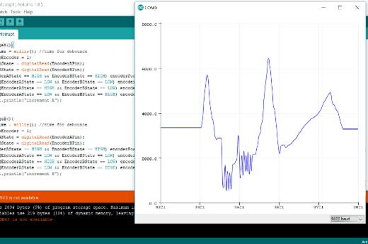
As with the optical encoder, the position should change without any sort of fiddling. For extra fun, open the Arduino IDE’s serial plotter at the same baud rate. Instead of merely telling you the position numbers, it will create a graph of the values automatically.

Whether you use them as a custom interface or to measure speed and distance, encoders provide an excellent rotary input method for your Arduino project. They take a little more work to set up than many other types of devices, but the results can be well worth it.


