Shunt resistors make up a category of resistors that create a low resistance path, and they are widely used to measure high currents thanks to their low resistance.
Current measurement is required in many applications. For example, applications like over current protection, 4-20mA systems, battery chargers, high-brightness LED control, H-bridge motor control, or metrology need to monitor current.
Shunt sensors tend to be easier to design, and they are also cheaper than magnetic current sensors. However, they do not provide any isolation. Indeed, a rogowski coil or a Hall effect sensor is a noninvasive measurement where the sensing circuitry is not electrically connected to the monitored system and is then isolated.
How to Calculate Shunt Resistance
The technical constraints of shunt resistors differ from those of standard resistors. They are high-precision resistors with a low ohmic value (they can be expressed in microOhm when several hundreds of Amper currents must be measured). As accuracy is critical, current sensing is best achieved with a Kelvin connection (or four-terminal connection (see figure 1) that removes the unwanted influences of lead resistance and lead sensitivity to temperature.

Image: Four-terminal connection equation
Several factors can change the value of a shunt resistor, and they are split between reversible and irreversible effects. Long term stability is an irreversible change in resistance due to mechanical, electrical, and thermal loads. Reversible effects consist of mainly 2 components:
- Temperature Coefficient of Resistance (TCR): it is expressed in ppm/oC and characterizes the drift when the resistor is cooled or heated by a changing ambient temperature.
- Power Coefficient of Resistance (PCR): it is expressed in ppm/W and characterizes the power a resistor must dissipate.
Shunt Resistor Parameters
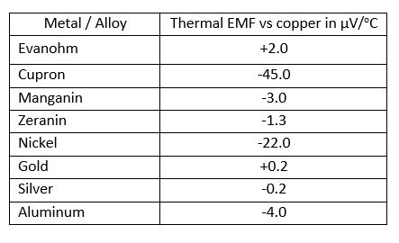
An important parameter for shunt resistors that is not significant for standard resistors is the thermal EMF. At the junction of 2 different conductive materials, a voltage variable with temperature (explaining why it’s called thermal EMF or thermocouple effect and expressed in µV/oC) shows up. The rate of change of voltage with temperature from an intermetallic junction is a function of the metallic combination. The sense of the voltage produced is either positive or negative on whichever side of the combination is being considered the input. It is presumed that all resistors are finally soldered to copper, and copper is then the reference metal. The following table shows some Thermal EMF values.
Table 1: Thermal EMF of the Metal vs. Copper

Table 2. TCR, ppm/oC of various Resistor Element Materials

Based on thermal EMF, TCR, and cost trade off, manganin is the favorite choice for shunts with exposed blades. Shunts with exposed parallel wires are made with zeranin, a relative of Manganin with a lower temperature coefficient. Shunts enclosed in heat sinks are generally made with Evanohm, which has a near-zero temperature coefficient with high sensitivity to strain. Vishay frequently uses its own technology called Bulk Metal Foil.
See related product
To conclude, choosing a shunt resistor depends not only on the resistor value and its tolerance. In order to ensure a reliable application, the long term stability, temperature coefficient, and power coefficient of resistance, form factor, Thermal EMF, and maximum power are key parameters to consider when selecting a shunt resistor.


