When you need to turn a grid of LEDs on and off, you can (of course) use a single IO pin for each, but at some point this become unmanageable. A traditional matrix setup is able to multiply controlled LEDs using an x/y grid, where the number of outputs under control is equal to IO(x) x IO(y).
LED Matrix: Multiplication of IO
So, a 3x3 grid could control 9 LEDs with 6 IO, and an 8 x 8 grid can control 64. This works because the IO(y) pins activate each row one at a time, and the IO(x) pins are set to either receive current to ground, or oppose this path. When each row is quickly flashed in sequence, the grid can be made to look like a matrix of solid colors.
Microcontrollers don’t just have the ability to set IO pins to positive and negative; they can also set them to be inputs. This third state—also known as high impedance, hi-Z, or tri-state—doesn’t allow current to flow either way, creating some interesting control possibilities. A technique called “Charlieplexing” (named after Charlie Allen at Maxim Integrated) takes full advantage of hi-Z, with LEDs arranged to pass current in either direction.
Charlieplexing: IO Exponentiation
While an LED grid multiplies IO, Charlieplexing is a more exponential relationship. The number of LEDs under control can be expressed by the equation n² – n, where n is the number of IO used to drive each LED. If you had 8 IO in a traditional, square x/y grid, that works out to 4 x 4, or 16 LEDs. With Charlieplexing, however, you can theoretically control 8² – 8, or 56 LEDs.
Notably, Charlieplexing can also be used to increase inputs. As with LED-based output, the cost is complication. Additionally, since the LEDs/diodes aren’t a part of the device’s function, one must factor this in when choosing whether it’s better to use extra IO, or set up a Charlieplexing circuit.
LED Multiplexing Circuit Tutorial

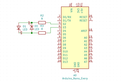
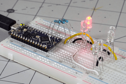
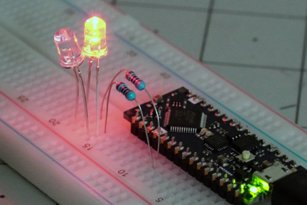
The minimum number of IO needed to drive a circuit using Charlieplexing is 2, and while the equation 2² – 2 = 2 means there’s no substantial advantage, it’s still instructive to explore how it works. In the above schematic, D1 and D2 are hooked across IO pins 5 and 6, with resistors inline. When pin 5 is high, and pin 6 is low, current flows across D1 and the LED lights up. When the reverse is true, only D2 allows current to flow, lighting up this LED, while D1 remains off. Hi-Z isn’t really used here, unless you want to turn both LEDs off, which could also be accomplished with both in IO in a logical high or low state.

Resistors shown here and in the other images are 150 ohms, but would ideally be half that.
One might argue that you’re saving a bit of wiring when compared to running each resistor to a ground individually, but the setup doesn’t really “shine” until you get to 3 or more IO pins. This behavior is also good to keep in mind in a pinch, if having an extra ground will simplify wiring. You can set one of your IO to low and use it for applications like sensing a button press.
An appropriate series resistor for the red LEDs used here would be 150 ohms, however, note that since you’re putting one on each I/O pin, the resistance will be doubled. Each LED would actually need to be half of that. In theory, each would be 75 ohms. One can also attach a resistor to individual LEDs, which is useful if you need to control LEDs with different voltage drops.
3 IO, 4 IO, More
Once you get beyond 2 LEDs, the benefits of Charlieplexing become much more evident, doubling the number of LEDs controllable with 3 outputs to 6, and tripling the number controllable with 4 to 12. What’s also evident is that the circuit becomes more complicated as well, with a wiring pattern that can be difficult to describe, shown in the circuit diagrams below.

Besides being difficult to describe, it’s also difficult to wire, hard to troubleshoot when something does go wrong, and not easy to program. While a great technique, these are all factors that must be considered when working with this IO-efficient method.
Charlieplexing Arduino: Code & Programming
In the Arduino IDE, output pins are set to either HIGH or LOW, with hi-Z requiring you to set the pinMode of the IO as an INPUT. Programming each pin this way would be a bit cumbersome, so, inspired by Brian Lough’s excellent video tutorial on the subject, I created a method found here to do this for me:
void charlie(int a, int b){
if(b == 2){
pinMode(a, INPUT);
}
else{
pinMode(a, OUTPUT);
digitalWrite(a, b);
}
}
With this implemented, in the main loop of the linked program, rather than remembering to set the pinMode, and/or write the correct state, one simply has to run the method with charlie(x, y);. Here x refers to the pin being modified, while the y values are 0 for low, 1 for high, and 2 for hi-Z or tri-state. Control of 6 LEDs with 3 IO pins as seen in the image below can be found here. One nice thing about this method is that extra pins can be added without explicitly declaring them as input or output; the method just takes care of that automatically.

Of course, this is only one layer of complexity for programming Charlieplexed LEDs. Ideally, you would create a method that takes care of the HIGH/LOW/hi-Z logic based on which LED you want to switch automatically. From there, you could get rid of or reduce delays in order to have each LED appear to glow at the same time, or use PWM to have them effectively brighten and fade.
Practical Charlieplexing?
With programmable LEDs, such as WS21812B units, and matrices driven via I2C like the MAX7219, and the like, one might wonder where Charlieplexing really fits into the scheme of things. First, one might note that simple LEDs are generally much cheaper than programmable versions, and since there’s no additional logic or other components, you can expect systems based on Charlieplexing to be more power efficient.
While the complexity of a Charlieplexed system would eventually get unwieldy, it seems that where such a system would really shine is in low-power applications where you need to conserve IO, and have a manageable number of LEDs that need to be switched. For an ATtiny85, for example, one could use 4 of its outputs to trigger 12 LEDs, leaving the fifth IO for other tasks.


