A charge pump is often used to turn on high side MOSFETs in an H-bridge topology. A voltage lower than application voltage Vs can be generated to turn on low side MOSFETs, where the low side is referenced to the ground, but the high side is referenced to a Vs that is the maximum voltage of the application.
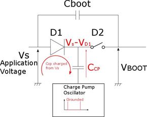
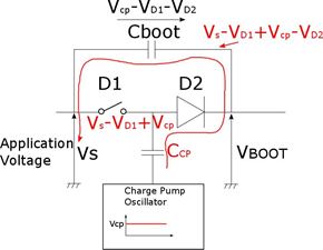
Hence a charge pump is necessary to apply a voltage higher than Vs on the gate of the MOSFET. This can be done by charging a capacitor Cboot with a voltage equal to Vcp. This voltage comes from an internal oscillator that switches between GND and Vcp with a typical frequency of several hundred kilohertz. The voltage Vboot is then equal to Vs plus Vcp and applied to the gate of high side MOSFETs. This first figure shows this schematic. Resistors can be added to limit currents in the circuit.

A charge pump follows the following principle: When the charge pump is grounded, capacitor Ccp is charged by Vs through diode D1.

When the charge pump oscillator voltage has risen to Vcp, D1 is reverse biased and Cboot is charged from Ccp through D2. After a few cycles, the Vboot voltage is equal to Vs+Vcp-VD1-VD2.

Figure 3
The charge pump oscillator oscillates at several hundred kilohertz so the D1 and D2 diodes must be of the Schottky variety. Legacy products, like the dual full bridge driver L6205PD, integrate a charge pump where Vcp is equal to 10V.
관련 상품 참조
BAV99 is a common and cheap Schottky diode that meets requirements for a robust charge pump design when the voltage swings between 0 and 10V.
In order to decrease cost and simplify production, many companies try to reuse designs and components that have proven reliable, especially in the case of components with common and simple designs like a charge pump. But taking even a simple design for granted can sometimes backfire. Let’s take the L6480—a two-phase, bipolar stepper motor driver where the charge pump can be programmed at 7.5V or 15V.
관련 상품 참조
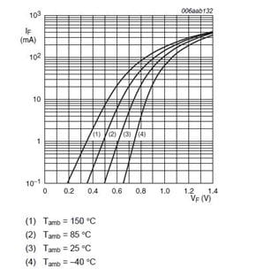
An engineer under time-to-market pressure might look at the BAV99 and think it would be a logical fit within the design. Unfortunately, this diode will not work under all conditions, making the debug more complicatedly than expected. In fact, the motor can stop unexpectedly with temperature changes. The L6480 has a protection circuit that stops the motor if the Vboot voltage is too low. As shown above, the Vboot voltage is equal at Vcp (7.5V for the L6480) minus 2 times the forward voltage of the diode. The BAV99 has the following specifications for the forward voltage:

Depending how the current is limited in the charge pump circuit and the ambient temperature, the forward voltage can range from 0.3V to 1.2V. In our example of the L6480, 7.5V – 2 * 1.2V = 5.1V, which is lower than the turn off threshold of 5.5V.
To solve this issue, a Schottky diode with a lower forward voltage is required. The BAR43 is a common diode where the forward voltage is at 0.5V under all conditions and Vboot will always be above the turn off threshold of the L6480.

This charge pump example demonstrates why no specification must be overlooked when designing an electronic circuit. A blind copy/paste of a design will probably produce intermittent failures. At 15V, the circuit works perfectly with the BAV99. At 7.5V, after system failure, you might end up spending a lot of time debugging what could have been avoided.


