Learn about the various markings on capacitors and the properties that these codes represent.
When you’re working with circuits, it’s essential to know and understand each of your components’ specs. Unfortunately, many parts, like capacitors, are too small to have all their relevant information written out in full. As a result, many manufacturers mark capacitors with essential data in shorthand or use visual markings that take up less space. The markings and data they’re able to write depend on the capacitor’s size.
Before we look at the markings themselves, let’s review some important terminology that will help us learn how to read capacitors:
- Capacitance: The amount of charge that the capacitor can store.
- Breakdown Voltage: The point at which the capacitor short circuits and can no longer hold a charge.
- Tolerance: The expected variations around the given capacitance – in other words, how close the real capacitance will stay to the designated capacitance.
- Polarization: By design, some capacitors can accept voltage in only one polarity (otherwise you risk destroying the device). In polarized capacitors, therefore, it is important to know which lead is positive and which is negative.
Common Capacitor Numerical Markings
- Capacitance
- Breakdown voltage

In this marking formula, it is important to note that the final digit may indicate a few different things:
- 1-6 indicate powers of 10
- Seven is not used
- The numbers eight and nine refer not to an exponential power of eight and nine, but to a multiplier of .01 (x 10-2) and .1 (x 10-1) respectively
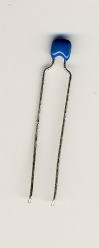
Note that tiny capacitors – under 1000μF – will indicate the capacitance directly in picofarads. You may see a number between 1 and 999 written directly on them. It’s important to know the general range of capacitance to understand how to read the numbers. You’ll need to know the difference between 134μF written directly or at 130,000μF written in an exponential coding.
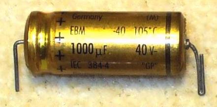
After capacitance, the next most important spec is the breakdown voltage. If the capacitor bears a second value, it will typically be its breakdown voltage, expressed as a number followed by V, such as “25V” or “100V.”
Finally, in the case of a capacitor with polarized leads, you’ll typically see a colored stripe on the negative side. Usually the line is white, but below you can see a capacitor with a black stripe marking the negative pole. Also note the indications for the breakdown voltage and operating temperature.

Capacitor Color Codes
Modern capacitors use the numerical markings we outlined above, but older capacitors employed a (now obsolete) color coding system. If you come across these capacitors, try looking up a capacitor color code guide like the one here to decipher the codes for capacitance, breakdown voltage, and other values.
Other Capacitor Values
Other optional data may include values such as:
- Operating temperatures
- Temperature coefficients
- Date of manufacture
- Tolerance
Component manufacturers indicate tolerance with a letter code that refers to variances as small as +/- 0.5pF (indicated as A) up to -20/+80% (written as Z). The capacitor tolerance chart below shows some common tolerance letter codes:
|
Capacitor Code |
Capacitor Tolerance |
|
B |
± 0.1% |
|
C |
± 0.25% |
|
D |
± 0.5% |
|
F |
± 1% |
|
G |
± 2% |
|
J |
± 5% |
|
K |
± 10% |
|
M |
± 20% |
With these guidelines, you should be able to quickly check the specs of any capacitor you are using. If you’re unsure about an unusual marking’s meaning, if the capacitor doesn’t indicate a crucial piece of info (such as the breakdown voltage), or if you’re designing a new project and specifying capacitors, check the complete datasheet to be sure you have what you need to proceed safely.

