It is impossible to design a circuit that is 100% invulnerable, but there are many things you can do to drastically lower the probability of system failure and, subsequently, any potential harm to the machine and/or user.
Common protection methods consist of ferrites for EMI reduction, ESD diodes, transient suppressors, interlocking processes for high-power loads, and, of course, fuses to limit current upon a fault condition. Safety can greatly increase the importance of these kinds of protection while requiring other safeguards as well. This article will dive into a variety of common protection and safety practices for electronic design and what drives their requirements. It turns out that protection may not only help improve the overall reliability and safety of a product but might actually be required for certification and product distribution based on the application.
Finding the right balance
Let’s begin with a very basic question: How do you find that balance between protection circuits and cost-effectiveness? For a product not requiring a specific kind of safety, how does the designer know when they should add in layers of protection? The answer can be complicated but should typically be driven by a culmination of the product user/design requirements and, simply, best judgement of the designer and associated team.
There’s typically a balancing act when it comes to cost and benefit when incorporating protection into a circuit, and it can usually be managed by estimating the relative risk. Fuses can be costly but are generally the first line of defense with regard to current surges that may stem from environmental variables or load-based components. The benefit here is the protection of everything downstream of the fuse, which, of course, can be very important. But what about other, smaller forms of protection? How about ferrites? It’s common to incorporate small ferrites on sensitive signals travelling off-board to help mitigate EMI and high-frequency noise, or for use on inputs to regulators or processing components to help clean up the voltage rail. The “insurance” policy they provide may be worth the additional cost if the risk is high enough. And risk here can be thought of as a combination of severity of a failure and the expected probability of its occurrence.
How and when to address safety
Everything becomes more straightforward when safety is considered. Cost typically decreases in priority while reliability and redundancy become the primary goals (and will likely be required during the certification and product testing process). For products that in certain failure modes can inflict any kind of harm on people (whether directly or indirectly), a risk assessment must be conducted to cover as many reasonable scenarios as possible.
For example, in health care, this is required for medical devices and becomes a bit more involved, including a table (as shown in Figure 1) covering each reasonable hazard, a description of its event/situation, the harm it could inflict, and its probability/severity rating. Each hazard then gets evaluated by a designated person (or group), becomes “controlled” by introducing additional design requirements meant to address each hazard (deemed unacceptable), and is re-rated and accepted. Though the dialogue might be a bit different for other applications (such as aerospace), the core principle is the same across many industries. Rating each risk with severity and probability and then controlling it with an action plan is the key to identifying areas in electronic (or any kind of) design in which safety and protection are necessary.
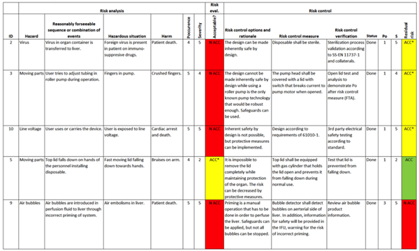
Figure 1: Hazard traceability matrix for risk management for a medical device
But how do these probabilities and severities get quantified and rated? Usually, this is achieved via a very detailed table explaining the differences between each numeric value specific to the application. Figure 2 demonstrates some examples of frequency and severity definitions to provide guidelines when a team is rating a hazard or event. The ranking range/values will vary based on the application and resolution needed.
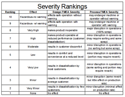
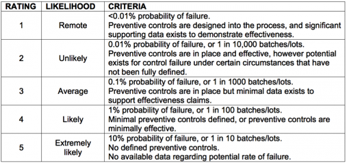
Figure 2: Severity ranking definition (top) and probability ranking definition (bottom) tables
And finally, there is typically a table that combines the two and can be color-coded (as shown in Figure 3) to easily visualize if a potential hazard needs to be addressed with design specifications and changes. Usually, Medium (yellow) and High (red) require some form of action. And thus, a safety circuit requirement is born.
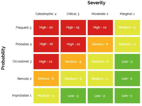
Figure 3: Risk matrix calculation table
Everything described thus far is common across industries that may have products or systems with critical operating features; however, it may not be needed for every application. Many times, it is as simple as using best judgement based on the use case and potential for damage or harm.
Most electrical products will need to receive some sort of certification of compliance before the technology can be produced, distributed, and sold. And that certification process will not only include electrical compliance but safety compliance as well. It’s a grey area, and sometimes, it’s not always clear what is needed for a product to pass safety compliance. Regulatory agencies will generally offer some support throughout the process, and it’s always best to involve them during the design stage.
Real-world examples
The following is an example of an application utilizing laser light for imaging purposes. Laser light can be very harmful to the human eye, and even stray light (reflected off of another surface) can be enough to cause damage or even blindness. While using special goggles can help, it’s typically required that a machine has some added electronic protection against misuse and unintended stray light. Interlocking doors and removable panels with circuits directly wired to the laser power (or an interlock/relay managing its power) is generally the best bet, but even these measures will require redundancy. The term is formally referred to as “fail safe.” If the safety circuit was to fail (i.e., any of the internal switches), it would need to fail in a safe condition so as to not harm the user or equipment, and this may result in a backup, redundant circuit.
Figure 4 demonstrates an interlock diagram that includes a signal (with enough power for a coil in a relay) travelling through several doors/covers on the machine and a keylock that adds a manual step to engage and disengage laser power (optional). The circuit requires redundancy, and so there are dual magnetic reed switches needed for each access point, as well as dual switches needed for each other component. If one of the internal switches inside a component fails in the “closed state,” it’s still considered safe, as the other internal switch (which is wired in line with the first switch) is very likely to be open, which will still cut power to the laser module.
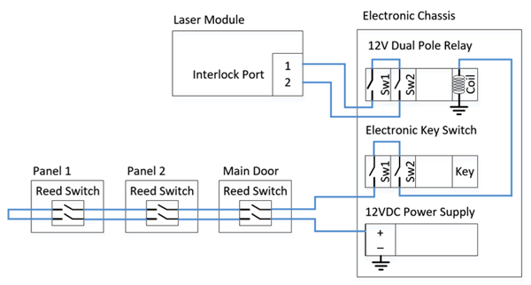
Figure 4: Example of a wiring diagram depicting a safety circuit for laser light
Another example consists of a heated medical device used on human skin. In this application, there is a potential for the heater to burn the skin if a runaway or mis-calibrated failure occurs. While not life-threatening, the potential outcome still warrants some fail-safe/redundancy features.
Figure 5 shows an example of this. There are several potential failure points, even in this very simple control circuit. Not only does the system contain a secondary thermistor for temperature sensing (in the event that one gets damaged), but multiple control points are needed in the event that either a MOSFET fails closed or a processor’s internal ADC is damaged or mis-calibrated. In this configuration, a small, very simple secondary processor exists for temperature monitoring and heater power control and operates independently of the main processor.
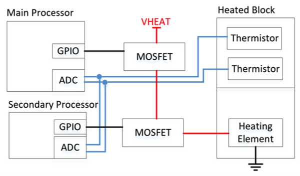
Figure 5: Example of a circuit diagram showing redundancy for a heating element
Figure 6 shows a variety of protection circuits that could result in a safer, more reliable device. “A” shows a fan control circuit that indicates when a fault is present, along with a fused power rail and added ferrite for EMI suppression. “B” includes a fused power rail for a servo motor, along with a current-monitoring device so that the processor can verify movement/power. “C” is an example of a USB connector used for charging purposes, with added protection for its VBUS rail (ESD and fuse). “D” is a simple reverse-voltage protection circuit for a 3.7-V battery connector.
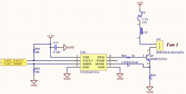
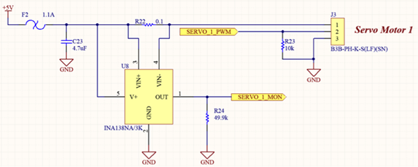
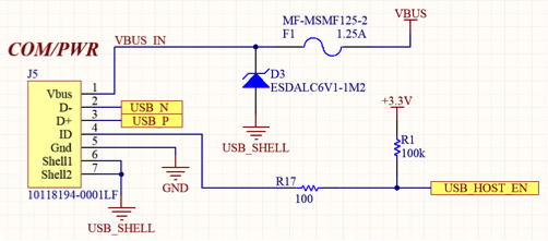
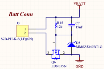
Figure 6: A variety of protection circuits
Conclusion
Protection and safety circuitry should always be considered but may, in fact, be required, depending on the application. For more severe cases, working to produce reasonable, potential hazards and assigning numeric ratings is half the battle. The other half involves an action plan with a set of detailed requirements, along with some good-old–fashioned design skills and “best practices.” And for all cases and applications, consider how a circuit failure may lead to harmful or damaging outcomes.


