If you’re a fan of WWII airplanes and other machinery of that era, eventually you’ll stumble onto the subject of gyroscopes. The M-7 gyroscope was a marvel of modern technology at the time, but it took up a lot of space. These gyroscopes were about the size of a small internal combustion engine.
Over 70 years later, these devices have undergone incredible miniaturization. You can find a gyroscope, accelerometer, and even a temperature sensor built into a single chip – called an inertial measurement unit (IMU) – that is even smaller than your fingernail. One very popular accelerometer is the MPU-6050 from InvenSense, which you can buy, along with a breakout board and all the components you’ll need to use it, for about a dollar.
This chip uses microelectromechanical systems (MEMS) technology to vary internal capacitance values based on external forces. While its inner workings are fascinating, the chip takes in all the sensing details. Feed the values it produces into your Arduino board or any other computing system that you choose. Conveniently, the chip puts out this data in an I²C format, allowing it to use two wires and an interrupt pin to sense:
- Acceleration data
- Gyroscopic data
- Temperature data
How to Use an Accelerometer with Arduino

Image by Jeremy S. Cook
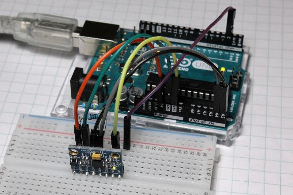
For this exercise, we’ll be using a GY-521 module that includes an MPU-6050 chip, piping data to an Arduino Uno. A wide variety of dev boards and computing systems are compatible with the I²C standard, so you should be able to apply these concepts in many situations, even if the specific pins and libraries you use are different.
For this experiment, we’ll first hook up the GY-521 board based on the following connections:
- VCC: +5V
- GND: GND
- SCL: A5
- SDA: A4
- XDA: Not connected
- XCL: Not connected
- AD0: GND
- INT: DIO 2
We also connected one 4.7kohm resistor between SCL and ground, and another between SDA and ground. You can find examples that don’t use an external resistor, so this may not be necessary for every application.
MPU-6050 Arduino Raw Data
Here are the basic steps to obtain the raw data:
- Once you’ve connected everything, load the “Short Example Sketch” found here on your Arduino board.
- Open your serial monitor and set it to 9600 baud.
You’ll then see the following values:
- AcX: accelerometer reading in the X direction
- AcY: accelerometer reading in the Y direction
- AcZ: accelerometer reading in the Z direction
- Tmp: temperature reading
- GyX: gyroscope reading about the X-axis
- GyY: gyroscope reading about the Y-axis
- GyZ: gyroscope reading about the Z-axis
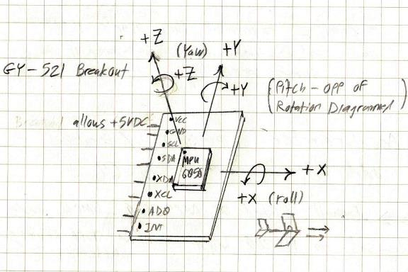
We’ve illustrated these axes and their orientation in the sketch below. Each value should respond when the device moves. When resting with the writing on the chip facing up, the Z-axis will read as positive, indicating the direction of gravity. If the X or Y axes face upwards, they will produce similar readings. The curves about each axis will indicate the roll values.
A note about roll direction: it follows the “right-hand rule” that we encounter in physics. If your right thumb points in the same direction as an axis, your fingers will curve in the positive rotational direction.

Image by Jeremy S. Cook
Arduino MPU-6050 Connection: Sensor Fusion
You may be able to work with these raw values for many applications, but the MPU-6050 has another trick up its sleeve: The Digital Motion Processor (DMP). This processor can fuse the accelerometer and gyroscopic values for better accuracy.
InvenSense has largely been mum about how to use this data, but Jeff Rowberg’s extensive I2C Device Library (i2cdevlib) can take advantage of the DMP’s functionality using clever reverse engineering work. According to Rowberg, the code needs a few updates at this point, but he uses the MPU6050 library and the included MPU6050_DMP6 example code to produce clean values for yaw, pitch, and roll. You can also uncomment several options in the code to produce different outputs as needed.
After you load the code, follow these steps:
- Open the serial monitor and make sure to set it to 115200 baud.
- Enter a single character.
You’ll see output listed as “ypr” for yaw, pitch, and roll, with the X direction on the chip corresponding to what would be the front of an aircraft. Roll and yaw orient in the same direction as you’d expect from the raw values we discussed earlier. The pitch, however, is opposite. When a theoretical aircraft points its nose down, the pitch decreases, but when its nose points up, its pitch value increases. Phrasing things this way makes sense in a flying environment; an instructor telling you to “decrease your pitch” to take off would certainly cause confusion — or worse.
Whether you build model aircrafts, you’re devising a new game controller, or perhaps you just want to make sure your phone can properly auto-rotate, tiny IMU chips make all of this possible. With their low cost and pre-written Arduino libraries, custom applications are just a matter of plugging in a few wires and coding away.


