Diodes nominally conduct electricity in one direction, and the voltage they apply follows a so-called “forward bias” orientation. If the voltage moves in the opposite direction, we call that orientation a “reverse bias.” In reverse bias, current flow is nominally blocked as a sort of electronic check valve.
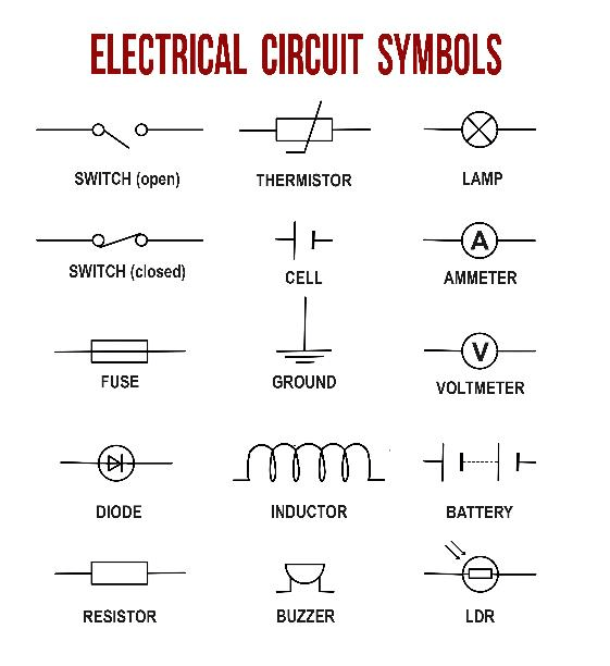
Diode Markings & Electrical Circuit Symbols Overview
Diodes are generally marked with a line that runs perpendicular to the terminal direction. This line indicates the negative direction when connected in a forwardly biased orientation. Symbolically, we represent a diode arrow pointing from the positive forward-biased terminal to a line at the negative terminal.

The arrow indicates conventional current flow notation, though the electrons actually flow in the opposite direction. Ironically, the electron flow through this symbol matches pneumatic check valve more closely, just without the little circle ball symbol that’s trapped in the triangular funnel.
How Does Diode Bias Work?
So how does diode bias work with no physical “rubber ball” to stop electrons from spilling out? As you might suspect, the answer is rooted in electromagnetic physics. A diode is generally constructed with a positively charged P-type semiconducting material, along with a negatively charged N-type semiconductor, attached to each other via a nominally charge-free depletion region.
- When forward biased with a charge of between around .3 and .7 volts, the depletion region shrinks, allowing for the flow of electricity.
- When reverse biased, the depletion region expands, not allowing current to flow unless overloaded to the point of failure.
In a forward-biased situation, the P-type semiconductor region connects to a positive power supply voltage, effectively pushing it into the depletion region. A negative voltage is in turn applied to the N-type semiconductor, and as negative charges repel, they push electrons into the depletion region and closer to the P side of the diode. The circuit is complete once the diode is sufficiently forward biased and electrons can flow.
With voltage moving in the opposite manner, the positive and negative semiconductor regions pull further apart, increasing the influence of the depletion region and disallowing current flow.
Why Zener Diodes Work in Reverse Bias
Power can flow in the reverse biased direction over diodes. However, a reverse current flow typically means that the diode is overloaded voltage-wise and has failed—perhaps violently. Zener diodes, however, are designed to allow voltage flow in forward-biased direction in the same manner as P-N diodes. When this bias is reversed, the Zener diode allows current flow at a certain carefully controlled voltage level.
These diodes operate at 5 volts or less, though a similar component called an avalanche diode works the same way at higher voltage levels. Their ability to perform reverse current flow can be very useful to modify voltage signal outputs, and these types of diodes are therefore an essential part of many designs.
If you need a current one-way valve, the forward and reverse bias behavior in diodes makes them the perfect component for the job. Zener and avalanche diodes expand this ability even further. We can use specialized diodes such as these for applications that go far beyond protecting sensitive components from voltage reversal.

