Before the dawn of communication satellites, humans navigated using the stars, maps, and even the land-based LORAN (not to be confused with LoRaWAN) navigational aid. Once Sputnik started traveling the globe and emitting radio signals, engineers realized they could use multiple satellite signals to triangulate a person’s position on earth. From this realization, and after a massive amount of work, the United States developed the satellite positioning system that we now know as the Global Positioning System, or GPS.
This system, along with its more recent international counterparts, has evolved from exotic to a ubiquitous and inexpensive technology available on your average cell phone. For those that wish to use the tech in their own projects, GPS modules are available by themselves without a screen or mapping software.
You can set up a GPS module to feed position and time data to your Arduino board over a serial connection, and these devices are easy to set up. Several libraries are available to help you turn this raw data into useful information, and this article will outline a few experiments to get you started with this technology.
Arduino Uno GPS Project Materials:
- Arduino Board (we used the Uno)
- u-blox NEO-6 GPS module and antenna
- USB-TTL serial cable
- WS2812B “NeoPixel” RGB LED & jumper wires
- Software, as outlined in this article
Getting Started: How to Check if GPS Module is Working

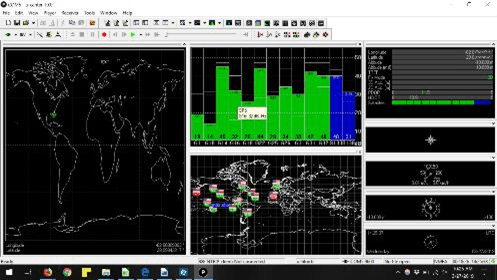
Caption: U-blox software. Note the green connection icon in the upper left portion of the screen
We’re focusing on using a GPS module with Arduino, but you should begin by making sure the GPS is operating properly.
1.Connect the antenna to the GPS unit.
2. Solder header pins as needed to the GPS module.
3. Connect the USB-TTL cable to your computer.
4. Connect the power and ground from the cable to the power and ground of your USB module.
5. Connect the TTL Rx cable to the GPS Tx and the TTL Tx to the GPS Rx.
To make sure you’re receiving some sort of signal, open the com port with the Arduino IDE (install this if you don’t have it) and set it to your GPS baud rate (we used 9600). You probably won’t understand the data output, but if the GPS is receiving or outputting a serial signal, you will see some sort of “proof of life” indication. To further inspect your GPS functionality, follow these steps:
1. Download the u-blox software.
2. Connect via TTL and select the appropriate com port as on the Arduino IDE.
3. Connect via a plug icon in the upper-left portion of the interface.
Now you can view position data, satellites overhead, and your rough map position clearly.
If you’d like to verify accuracy, plug the data into the Google maps search bar in the numerical format: latitude, longitude. You’ll receive a reading a few feet from your current location, possibly even indoors.
GPS Module Arduino Connection

Next, follow these steps to connect your GPS module with your Arduino board:
1. Download the TinyGPSPlus library from GitHub, then add it as a .zip library on your Arduino IDE.
2. Open “DeviceExample” under examples and change the GPSBaud to the proper rate for your device (device tested was 9600).
3. Send this code to your Arduino board.
4. Connect the VCC GPS pin to the GPS +5V pin from the Arduino and GND to GND.
5. Connect Rx to Arduino pin 3 and Tx to Arduino pin 4.
6. Open a serial port at 115200 baud, and you should see latitude and longitude coordinates, followed by the date and the Coordinated Universal Time (UTC), which you will need to adjust to your location.
7. To confirm your setup, verify your location with Google maps.
Using Arduino GPS as a Speedometer

Caption: Arduino GPS stopped on a desk.
With an Arduino board, you can use your GPS module to advance beyond reading coordinates; you can even set up your device react to its conditions. The TinyGPS library makes a variety of time and position values available.
For this experiment, we’ll use its ability to output speed in kilometers per hour to change the color of a WS2812D RGB LED according to how fast it’s traveling.
- Red will signify stopped movement (a speed value of 0)
- Yellow indicates speeds up to 5 kilometers per hour.
- Green is for any greater speed than 5 kilometers per hour.
You can modify or expand these values as needed, but as written they correspond to values you can easily attain on foot. Follow these steps to set up your speed light demo:
1. Install the Adafruit NeoPixel library.
2. Download and install Speed-RGB.ino from this directory.
3. Connect a single RGB light’s digital input to Arduino pin 5, ground to ground, and the +5V pad to +5V on the Arduino board. If this interferes with the 5V supply your GPS module, you may be able to power it with the Arduino’s 3.3V source instead.


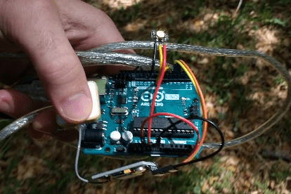
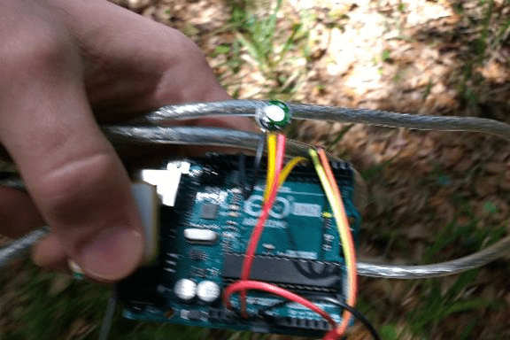
Caption: Stopped, slow walk, faster walk/run. Note the blurriness that increases with speed
Install the sketch on your Arduino board, then move it around to see if you’re getting light feedback. The code also includes serial outputs, so if it doesn’t work properly, you can open a serial monitor to help determine the problem. If you don’t want to bother with an RGB LED, one alternative program is called “GPS-Builtin-Blink.ino,” and it’s available in the same repository as the RGB routine. It uses the LED built into most Arduino boards, but it will only show if you’re stopped or moving.
While an entertaining first step, an operating a speed light demo only offers a taste of what Arduino boards can do when paired with a GPS module. Notably, while TinyGPSPlus appears to be a very capable library, you have plenty of other available software options, as well as different hardware to suit your needs.


