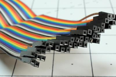
Depending on the context, "header" can have a wide variety of definitions. It could refer to the information at the beginning of a block of data, an automotive component, or even a way to strike a soccer ball. Here, however, we'll be talking about pin headers and corresponding female headers that you can use to connect small wires to circuit boards. These are occasionally referred to as "Berg connectors," named for a company that makes this type of device.
Pin Header Connector Basics

Image: Jeremy S. Cook
Pin headers are stiff metallic connectors that are soldered to a circuit board and stick up to receive a connection from a female socket. While pin headers (often called PH, or headers) are male by definition, female equivalents are also quite common, and we refer to them as female headers (FH) or header connectors.
A plastic structure holds these sets of pin headers together. This structure is often designed to snap apart as needed, though female headers are generally manufactured with a set number of pins.
We define headers by combining:
1. The number of pins in a row.
2. An "x."
3. How many pins wide it is.
So an 8x2 header would stack eight pins in a row, with two rows of pins attached beside each other, for 16 connections in total.
We also define headers by the spacing (pitch) between connections, with 2.54mm (.1in) being typical. Other sizes are also available, like 1.27mm (.05in) or 2.00mm (.079in). Headers are normally through-hole devices, but you can also find surface-mount technology (SMT) headers. While straight headers are the norm, 90-degree pin headers are also common to accommodate various physical requirements.
Additional Pin Header Uses

Image: Jeremy S. Cook
In the image above, the object on the right is a standard female header that can be soldered onto a through-hole PCB. On the left is what's known as a stacking header. While they act as female headers, the male pins' extended length connectors allow it to reach through the PCB and connect to another female header underneath — which means you can stack boards or connections on top of one another.

Image: Jeremy S. Cook
You can also pair headers with jumpers to create semi-permanent input devices. The photo above shows three jumpers, each one connecting two male headers together to form a connection.
Pin Headers Applications
With that information in mind, where are you likely to see these headers? Here are a few examples from my personal parts stash. What you observe will, of course, be different.
Images: Jeremy S. Cook
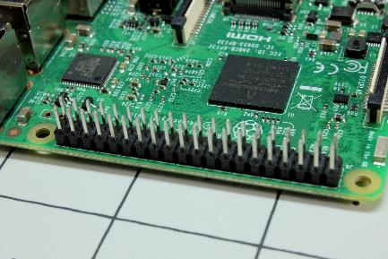
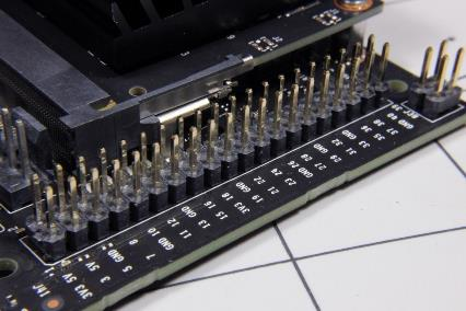
The Raspberry Pi 3 features a 40-pin GPIO connector in a 2x20 pin header arrangement. The Jetson Nano also features such a GPIO connector, as seen in the second image (black PCB), making it possible to share some accessories between the two.

Images: Jeremy S. Cook
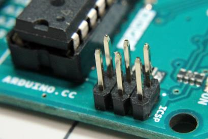
Arduino Uno female pin headers on display, along with a close-up of its 3x2 ICSP (In-Circuit Serial Programming) pin header arrangement.
Box Headers: How They Differ From Female Headers
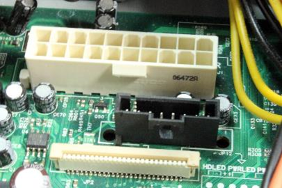
Image: Jeremy S. Cook
We haven't discussed one connector sub-class: the "box header." Box headers surround pin headers with a rectangular enclosure. Not to be confused with a female header, this wall around male pins can keep the connector in place, and each box header normally has a notch that prevents reverse connector insertion. Another anti-reversal technique is using a polarizer pin header arrangement:
• One pin in the connector socket is filled in.
• The corresponding pin is clipped.
• When the connector is reversed, this "blanked out" connection prevents insertion.

As for what plugs into male headers, the first two images above show an example for the Raspberry Pi 3A+ (neither a box header nor one with anti-reversal features): 40 wires connected at one time. If you'd like more control of what goes where, you can buy single "Dupont" connectors, as shown in the final image. If your project calls for it, you can even create your own in custom arrangements.
