
Analog electronics employ three basic, linear passive components: the resistor (R), the capacitor (C), and the inductor (L). These three components create four basic circuits: RC, LC, RL, and RLC. The circuits’ names indicate the components involved.
RC circuits and their behaviors form the basis of many analog electronics, and passive signal filters rely on them extensively. The RC filter, as we will see below, commonly blocks out unwanted frequencies.
What is an RC Circuit?

The purest form of an RC circuit consists of a resistor and a capacitor connected in parallel with a constant DC power supply. When someone disconnects the power supply, the current discharging from the capacitor is equal to the current through the resistor. The voltage decreases exponentially with time, and the time required for it to discharge fully is five time constants, or Ƭ.
RC Circuit Formula to define Ƭ as follows:
![]()
In this case, we express Ƭ in seconds, R in Ohms, and C in Farads. It will take five time constants to fully charge the capacitor in a similar circuit with the resistor in series between the power supply and capacitor. It is important to note, however, that “fully” is an approximation. The amount of charge we applied over five time constants accounts for about 99.3 percent of the maximum charge. At that point the flow of charge is negligible, and we can consider the capacitor “fully” charged or discharged.
RC Power Supply Circuits
A capacitor with stored charge can smooth out a variable power supply. If a capacitor outputs a square DC waveform, the capacitor can:
- Charge during the powered cycles
- Discharge while the power level is zero
The time constant will dictate how well this smooths the output of a circuit. If the period of a power cycle is greater than 5Ƭ, the output of the circuit will still approach a zero value. The higher the time constant of the circuit, the closer the output will be to a perfectly smooth DC.
RC High-Pass & Low Pass Filters

Image via Wikimedia Commons
Because it takes some time for a capacitor to charge and discharge, these devices are ideal for use as frequency filters. To function as a low-pass filter (also known as an RC Integrator), a voltage source connects directly to a resistor, and a capacitor connects in series with the voltage output as shown in the figure above. In this scenario, because the capacitor never reaches a full charge when the input frequency is too high, the capacitor can intercept current that would otherwise go to the output of the circuit as it pulses. As a result, the electrical output approaches zero above a particular frequency.
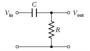
Image via Wikimedia Commons
An RC high-pass filter, also known as an RC Differentiator, works oppositely. The input signal applies directly to the capacitor with a resistor in parallel with the output, as shown above. By arranging components in this way, high-frequency signals can pass, while the capacitor blocks any frequencies that are too low. Therefore, the capacitor acts as an open circuit if the oscillations stay above a minimum speed.
RC circuits are one of the four basic circuit types fundamental to analog electronics. In their purest form, they consist of only two components. Despite their simplicity, we can exploit the relationship between these components for a variety of applications.