What is an Op-Amp?
You’ve probably heard the term “op-amp” thrown around in electronics jargon, but what are these components? Operations amplifiers — op-amps for short, are integrated circuits, constructed mostly out of transistors and resistors. These integrated circuits multiply an input signal to a larger output. You can use these components with voltage and current in both DC and AC circuits.
Karl D. Swartzel Jr. invented the first op-amp in 1967, and he originally conceived them to do mathematical operations in analog computers — thus the “operation” part of their name. We now use op-amps in many other applications, and they form the basis of many modern analog electronic circuits.
What Does an Op-Amp Do?
At their most basic, an op-amp takes a differential signal — the voltage difference between the V+ and V- pins — and outputs a voltage proportional to this difference through the Vs+ and Vs- power supply. You can see the Vs+ and Vs- power supply in the image below. Many simplified representations of this component omit the Vs+ and Vs- nodes and only show the V+, V-, and Vout pins.

Fig 1: Op-Amp circuit diagram symbol
This open loop operation typically results in a device gain (known as the open loop gain or AOL) of 100,000 or more. Even a tiny difference in the voltage on the non-inverting (+) and inverting (-) pins works out to an output of nearly the supply voltage when the + input voltage is greater than the — input. This configuration acts as a comparator, turning a potentially varying input signal to a steady on/off output.
Closed-Loop Op-Amps
We usually use op-amps in a closed-loop configuration, with the output voltage feeding back (as feedback) into the inverting input to form a more controllable signal amplification. The simplest way to accomplish this is to use a buffer circuit, where the output feeds back into the inverting input with no resistors or other components.
To understand how this operation works, here are the two op-amp golden rules:
1. The output attempts to make the voltage difference between the inputs zero
2. The inputs draw no current
Here’s how to construct a closed-loop op-amp:
1. Feed the input voltage into the + input
2. Connect the – to the amplifier’s output
3. The output should go to the same value as the + input to keep both equal

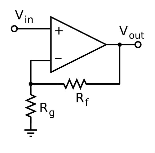
Fig 2: Op-amp with a feedback loop and voltage divider
In the image above, we took the closed-loop configuration concept further. If you want the output voltage to be a different value than the input, add a pair of resistors to form a voltage divider for the feedback loop. Amplification is thus based on the voltage we see at the node between these two resistors, calculated by the following formula:
Vin- = Vout * Rg / (Rg + Rf)
By this formula’s logic, we can state the following:
Vout = Vin- * (Rg + Rf)/Rg
Vout = Vin- *(1 + Rf/Rg)
The 1 + Rf/Rg term is the closed-loop gain (ACL) of the circuit. If the resistors stay the same as Vin increases or decreases, Vout will vary proportionally by a factor of ACL up to the supply voltage.
Other configurations are also available, including feedback to the inverting pin, and using a voltage divider circuit to allow an op-amp to provide negative and positive voltage.
Op-Amp Differences
Beyond being able to connect and use op-amps in different ways, you can select op-amps with a variety of specifications to fit your application, including variations on:
- Offset voltage
- Maxim supply voltage
- Gain-bandwidth product
You can find a wide variety of other op-amps available in different packages and with different specifications. Take, for example, the LTC2063 from Analog Devices, a low-supply current op-amp available in a variety of packages -- great for a variety of applications.

