Many systems require a clock input, and some RF applications require several unique frequencies that must be available quickly and with high accuracy. While direct analog synthesis (DAS) methods have been used for decades, direct digital synthesis (DDS) techniques have been rising in popularity since the 1970s.
Phase Locked Loop Basics
All closed loop analog controls operate on the same theory whether controlling a motor or a vacuum tube oscillator. There is a plant (the thing being controlled), an input dictating the desired output condition, a measurement or accumulation block to determine the error (how far off the output is currently), and a control block capable of actually altering the behavior of the plant to get the desired output. The control block is often combined with the plant in the basic diagram, because adjusting the controlling element is so clearly coupled with adjusting the output of the plant.

Phase-Locked Loop control operates like a standard control loop around a plant. The first PLL circuits controlled vacuum tube oscillators, but modern chips are designed for on-board crystal control.
The type of frequency generator required is a voltage controlled oscillator (VCO) and many ICs integrate this into the device, requiring only common passive components to operate. Devices like the MC14046B from ON Semiconductor include phase comparators, a VCO, a source follower, protective diodes, and filtering circuitry to generate buffered outputs that can be used like the output of a standard oscillator.
See related product
The input to the VCO is defined by the external resistors and capacitors chosen by the designer. Thus, using a variable resistor like a potentiometer gives user control over the output frequency.

PLL Control Loop from ON Semiconductor’s MC14046B Datasheet
What is VCO?
A VCO is exactly what it sounds like – an oscillator that can change frequency based on an input voltage. They are often based on a crystal, which can introduce issues like temperature induced frequency shift or high jitter. The control loop itself is at the mercy of the speed of the analog components and may not be fast enough for some designs. The range and granularity of synthesizable frequencies also may be insufficient for modern systems, especially those in the communication space.
Frequency Synthesis Using PLL Theory
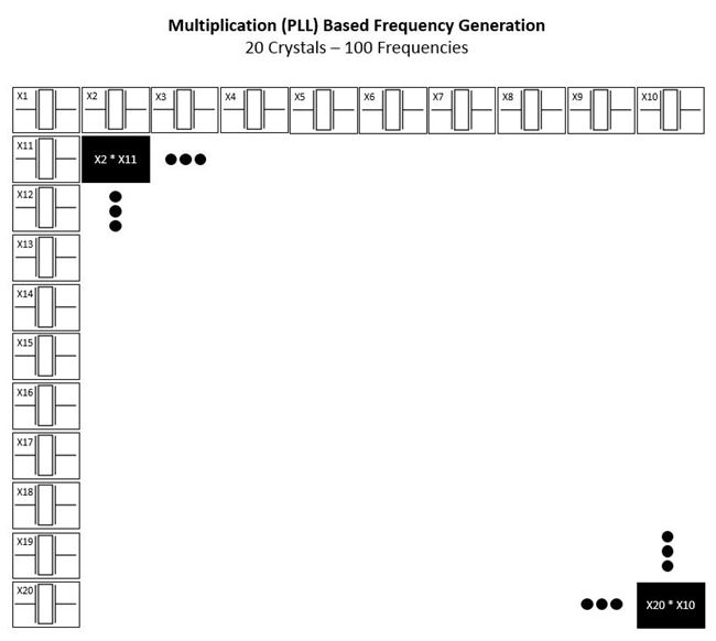
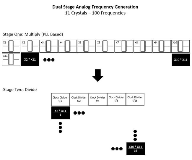
There are two common synthesis architectures based on PLL frequency control. PLL essentially lets you multiply two frequencies to get a new frequency that is not necessarily a direct harmonic of either original frequency. This means that instead of using 100 crystals to get 100 non-harmonic frequencies, you can use 20 clock sources by just using multiplication. This would really involve more than just 20 phase comparator ICs to get true dynamic frequency agility, but the BOM cost and board space would both decrease from using 100 crystals.

This multiplication-only technique is called multiply-filter or mix-filter architecture. The more complex version is called mix/multiply-fix-divide and uses both multiplication techniques and clock dividers.

A clock can be halved, quartered, etc. using standard logic, and there are several families of ICs available that allow you to choose the level of division dynamically. These ICs also commonly provide phase matching and buffering to maximize the immediate usefulness of the output signal.
See related product
While analog synthesis techniques work beautifully in theory, there are implementation challenges that encouraged the industry to keep researching better solutions. A mix-filter design is an elegant alternative when compared to a switched oscillator bank because it uses several fewer oscillators while maintaining phase memory – the trait that allows the synthesizer to maintain the phase of the original frequency through to the output. This is often disrupted when using a mix-filter-divide architecture. Not all applications require precise phase matching, but the resultant “hiccup” in frequency when a generated wave starts back at ø=0 is less than ideal for highly precise scanner systems, among others.
Direct Digital Synthesis – DDS Function and Performance
DDS is the pizza of signal synthesis. Each individual component or ingredient has been around for a very long time and has been used independently in a diverse range of applications, but the combination of the various parts created a product that has taken on a life of its own and is appropriate in just about every situation.
Although a direct digital synthesizer is sometimes called a Numerically Controlled Oscillator (NCO) as compared to the VCXO used in analog synthesis, the term “oscillator” is technically erroneous as no part of the device itself actually oscillates. Rather, digital components create a sampled waveform that can be run through a Digital to Analog Converter (DAC) to approximate a true analog sine wave.
DDS ICs require an input from a processor called a “tuning word.” The bit width of this tuning word defines the maximum possible steps the DDS can create. This input and a single known clock frequency enter the phase accumulator: a device that acts as the error block would in an analog control system and performs discrete mathematical integration. The output of the phase accumulator is a binary (or decimal, in some advanced architectures) word that enters a sine mapping look up table. The LUT is basically just a chart stored in memory, and the output of this stage is a digitally constructed sine wave approximation. The sampled waveform is then put through the DAC and external filtering circuitry to create a smooth analog sine wave.
The strictly digital components can operate strikingly quickly and accurately compared to an analog synthesis solution, often limited by the accuracy of the input clock rather than any limitations imposed by the accumulator or memory. However, the DAC introduces issues like signal degradation and a signal speed bottleneck yet is required to produce a useful waveform. Thus, the DAC is typically the performance limiting component within a complete DDS. Manufacturers like Analog Devices use techniques like multiple high bus-width DACs to achieve high performance.
See related product
The Bottom Line for Direct Digital Synthesis
Overall, a DDS can offer much higher performance over a wider range of frequencies with finer granularity, but it is often a more expensive solution that requires a more advanced understanding of synthesis to effectively integrate into a design. Slower systems requiring multiple frequencies may still find success with a simple PLL based analog synthesis technique, but DDS technology has completely revolutionized the way high frequency, high speed, and high accuracy systems get their generated clocks.
Want to know more? Watch our concise overview: What is Direct Digital Synthesis?


