November 1, 2021 by Maurizio Di Paolo Emilio
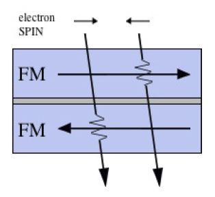
A TMR sensor element is made up of an extremely thin nanometer-level non-magnetic insulation layer, sandwiched between two ferromagnetic layers.
Today, several techniques able to convert a magnetic field to a proportional voltage are available. Magnetic sensors have been used in different applications across a variety of sectors, including magnetic encoders, e-compasses, absolute angle sensors, simple on/off switches, and current sensing.
The Hall effect, first discovered by Edwin Hall in 1879, has been successfully and widely used for many years to build solid-state magnetic sensors. However, it has reached some limitations that are forcing system designers to develop new technologies able to achieve target requirements, such as low power consumption, high sensitivity and accuracy, and affordable cost.
New technologies able to meet those requirements are based on the magnetoresistance (MR) effect, which is the property of a material (such as iron, nickel, and cobalt) to change its electrical value under a magnetic field. Changing the magnetization of a material alters how electrons travel inside it, resulting in a change in the device’s electrical resistance. The MR effect has different features depending on how the magnetic material’s interior was magnetized.
A novel technology spun off from MR is the tunnel magnetoresistance (TMR) effect, discovered by Professor Terunobu Miyazaki in the 1990s. As shown in Figure 1, a TMR sensor element is made up of an extremely thin nanometer-level non-magnetic insulation layer, sandwiched between two ferromagnetic layers. Electrons pass through an insulating layer from one ferromagnetic layer to the other. This is an example of quantum mechanics in action. When the magnetization directions of the two ferromagnetic materials are parallel, resistance decreases, whereas when they are anti-parallel, resistance increases.

Figure 1: A TMR junction composed of two ferromagnets and a tunnel layer (Source: Crocus Technology)
Crocus XtremeSense TMR technology
Crocus Technology offers a wide selection of magnetic sensors based on its patented XtremeSense TMR technology in industrial and consumer electronics applications. XtremeSense TMR technology is at the core of the Crocus magnetic sensor family, which includes integrated magnetic switches and current sensors.
According to Crocus, the main advantages offered by XtremeSense TMR technology are:
- High SNR (5-mA resolution in current sensors)
- Low power consumption (110 nA in switches)
- Temperature stability (less than 40ppm/°C)
“The demand for current sensing continues to increase, especially for architectures that need to run faster, be more accurate, and have less latency — that’s where we really see the introduction of Crocus devices,” said Tim Kaske, vice president of sales and marketing at Crocus Technology.
TMR offers several characteristics that allow for its use as a current sensor. Due to the TMR effect, a TMR sensor’s resistance changes according to the external magnetic field. When combined with state-of-the-art CMOS circuitry, TMR-based sensors can be used as high-SNR sensors with excellent linearity and thermal performance. These characteristics of the TMR sensors allow for its use as a contact or contactless current sensor.
TMR sensor applications
A key TMR sensor application that needs accurate and reliable current-sensing solutions is power-factor correction (PFC), a circuit that has become mandatory in many power applications (such as power supplies) to increase the efficiency and, for the same reason, is required by international regulations, such as EN61000-3-2 in Europe. A power supply including a PFC stage can supply higher output load currents than those without power-factor correction. PFC can significantly reduce the AC current harmonics, leaving almost only the “fundamental” current frequency, which is in-phase with the voltage waveform.
“We really see how one of the key focus [TMR sensor] applications that we are moving into is the CCM totem-pole PFC with GaN MOSFETs,” said Kaske. “I would say the PFC stage has not had a lot of updates in the last 10 years, but now, with the totem-pole architecture and new controllers able to support it, new opportunities are opening, such as EV on-board and off-board chargers, computing, and data centers.”
Standard current-sensing solutions, such as those based on shunt resistors, amplifiers, and digital isolators, are showing several limitations that can be overcome by using TMR current sensors, shrinking the footprint on the PCB by 2× to 5×.
“Other engineers, who have been using a Hall-based sensor for current sensing, are now seeing that we can offer a significant advantage for their system on accuracy, bandwidth, latency, and overall efficiency,” said Kaske.
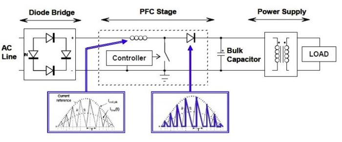
The block diagram of a typical active PFC is shown in Figure 2. The diode bridge converts the input AC voltage into a DC voltage, while the PFC stage is inserted between the line and the main converter. It acts as a pre-converter (normally a boost converter), drawing a sinusoidal current from the mains and providing in output a DC voltage.

Figure 2: Diagram of a typical active PFC stage (Source: Crocus Technology)
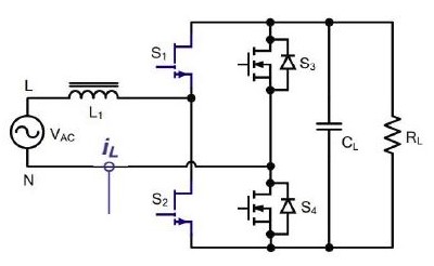
The CCM totem-pole PFC, shown in Figure 3, uses two GaN MOSFETs, S1 and S2, configured as a high-frequency half-bridge. S3 and S4 are line-frequency–led with synchronous MOSFETs. The main benefits arising from the adoption of this solution are high efficiency, low power losses, and reduced number of components. The higher-frequency soft-switching solutions require a current sensor that can detect fast transients to prevent potential cascading failures. This circuit uses just one bidirectional current sensor (iL) for sensing current on positive half-cycle and negative half-cycle.

Figure 3: CCM totem-pole PFC (Source: Crocus Technology)

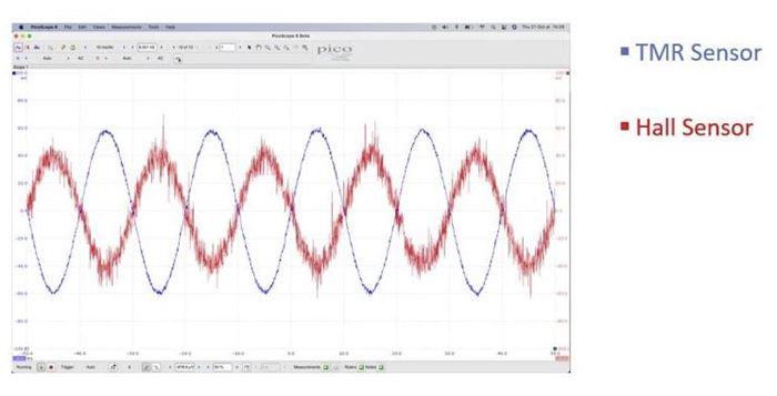
Figure 4: TMR sensor vs. Hall-based sensor (Source: Crocus Technology)
According to Crocus, an XtremeSense TMR sensor is the ideal solution for this application, as it provides:
- High SNR and clean signal to the controller
- Low power loss through the current-carrying conductor
- 1-MHz bandwidth with low phase delay and fast output response time (300 ns) for measurements
- Programmable overcurrent detection and fault pin to provide current information to the MCU
- Measure of both positive and negative current with bidirectional sensing
- High-voltage isolation (5 kV) to ensure safety
“Another market where we see great opportunities is solar power, a sector where current transformers, providing high safety and good isolation, are widely used,” said Kaske. “We think it’s a market where we can compete with contactless current sensors, offering the same or better isolation and higher accuracy.”
Browse a wide assortment of current sensors, hall effect sensors, current transformers and more from top manufacturers at Arrow.com.
See related product


