If your application requires communication between separate integrated circuits, I²C technology may be the solution. Since it emerged in 1982, I2C makes it possible to work with multiple nodes while only using two wires for signaling. This technology, also known as IIC or I2C – or, as a slightly different version, Two-Wire Interface (TWI) – is still in use today, and since 2006, users are free to implement it. You can find I²C in a variety of different technologies, including peripherals that work with the various Arduino boards available.
I2C Wiring: Setting Up the Physical Wiring
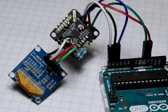
Image: Jeremy S. Cook
Let’s start first with the basics of what you’ll need to get an I²C module running. For this tutorial, we’ll assume you’re using an Arduino Uno, though you can use any Arduino or even a different computing system. Find more information on Arduino’s Wire library documentation, a piece of code that’s usually involved with I²C technology. Set up your board as follows:
- SDA (Serial Data Line): A4
- SCL (Serial Clock Line): A5
- Vcc: +5V, or potentially +3.3V depending on the module
- Gnd: Gnd
- Interrupt: Depends on the module and programming
You’ll also need to attach SDA and SCL to a positive voltage through a pull-up resistor. We use a 4.7kohm value for this setup, which is standard, but not essential. Some boards even include built-in accommodations for these resistors. Take note: you only need one resistor for each line, even if you’ve chained together multiple modules.
I²C modules include a default value for their address, but to set them up you’ll need to use jumpers or connect certain solder pads. If you’re unsure about your device’s address, and especially if you’re only going to use one I²C device in your project, use a program called Arduino I2C Scanner to see each connected device’s address.
Arduino I2C Example
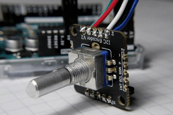
Image: Jeremy S. Cook
I²C technology can simplify and enhance many of your applications; we’ll demonstrate how to set up an I²C encoder as well as a small OLED display. We used an encoder I²C interface that comes as a small board with the I²C components. This interface does not include the encoder itself.
1. First, we soldered the encoder along with the five lines that would go to the Arduino Uno, all of which we plugged into the appropriate Arduino header pins.
2. This pinout stays consistent between most modules, but you’ll need to connect a fifth wire, labeled as “INT” for interrupt, to A2. This wire isn’t going to an Arduino interrupt pin; instead, it prompts the Arduino master to receive from the encoder slave module.
3. Once all the connections are in place, load the appropriate example code and a pair of corresponding libraries that must reside in the same directory as the sketch.
Depending on your device, you may need to change the address, which ranges from 0 to 127 in hexadecimal – expressed as 0x00 to 0x7F. You may also choose a different line to comment or uncomment depending on what type of encoder you use.
While the I²C format stays the same physically, the versatility of this bus means that there are quite a few variations on how to implement it on the software side. Finding the right configurations may require some calibration, but the potential savings in I/O and processor overhead make it very much worth the effort.
I²C Output
Neglecting the fact that the I²C encoder we used here has its own output possibilities – mostly in the form of added GPIO – what if you want to use I²C to receive visual feedback? One way to achieve this feedback is to use an affordable 128x16 pixel OLED display.
We’ll hook these devices up similarly to the rotary encoder. However, there is no “interrupt” pin in this setup since the tiny monitor is an entirely passive device, reacting to signals from the Arduino and not the other way around. We used a similar set of resistors between the SCL and SDA pins to the VCC pin, but you can find examples that don’t use resistors.
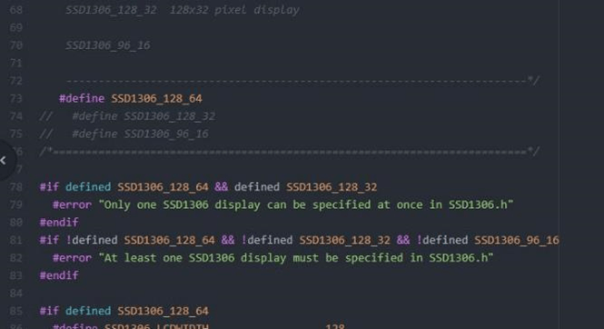
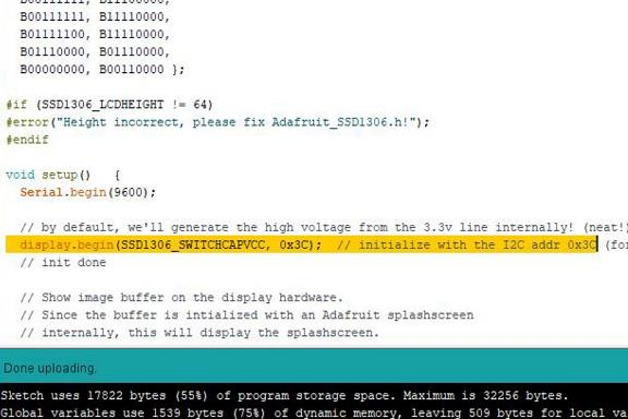
Image: Here are the minor code modifications you’ll need to get OLED screen working. By Jeremy S. Cook
To run the device, you’ll need the Adafruit SSD1306, along with Adafruit GFX libraries, both of which are available via the Arduino IDE library manager. Here’s the process:
1. Load the example program ssd1306_128x64_i2c to run the device.
2. As with the rotary encoder, you’ll need to modify a few components. First, change the height value in the Adafruit_SSD1306.h library to 128x64 by uncommenting the proper line using an advanced text editor like Atom. For my display, I had to change the I2C address to 0x3C from 0x3D to match up with its I²C value. We can generally find the proper value for this type of device using the I2C scanner.
3. Next, load the example program onto your Arduino board.
The program will cycle through its various screens and animations, offering an impressive display for a device that is so small and inexpensive. On the other hand, the OLED display doesn’t yet tell us anything about what’s going on in our system, which we’ll discuss in the next section.
One Wire I2C: Implementing a Dual Role
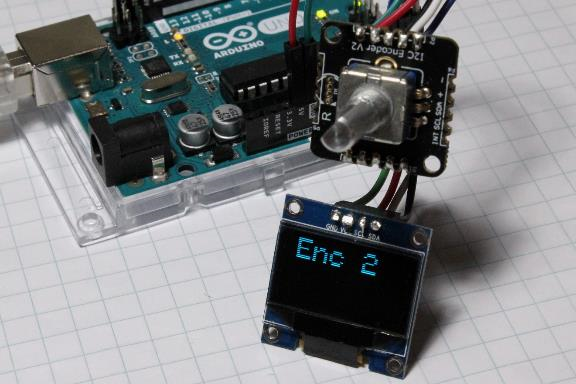
Image: Jeremy S. Cook
The encoder provides a numerical input and the OLED screen provides an output method, so why not combine the two? We wrote up some basic code for the encoder, which displayed the value on the scrolling text included in the demo. This application gives users a visual indication of how far the knob turns. Even better, we can use this same method to control multiple devices in an input or output mode over the same two lines. The encoder can pass power, ground, SCL, and SDA pins to the display, which means the Arduino requires no additional pins.
If you have limited I/O, this setup is an excellent option. Using this type of connection can help clean up your wiring, especially if you have been running multiple wires to each component. I2C devices often take some tinkering to operate correctly, but once you go through a bit of yak shaving, their versatility and simple interface can help streamline your project.
For another example of using an I2C component with an Arduino, check out this article about working with an MPU-6050 accelerometer.


