
In their most basic applications, capacitors store electrical charges, but we can also use them to even out or filter electricity. One early example of the capacitor was the variable capacitor, also known as the tuning capacitor. You won’t see many variable capacitors on the market today, but they once enabled us to perform important tasks like changing the radio station in an automobile. These capacitors have largely been phased out, but they do have some niche and educational applications that are still useful today.
Our technique shows how to make a 3D printed tuning capacitor using washers and other basic hardware. The resulting device’s capacitance will be in the 5 to 15 picofarad (pF) range, but you can expand the concept if your application requires higher values. If you don’t have access to a 3D printer, you can mock up a device based on this concept with wood, cardboard, or even plastic.
Materials You’ll Need to Make Your DIY Variable/Tuning Capacitor
Here’s what you’ll need to build your tuning capacitor:
- (2) 2” OD x 1/2" through hole washer
- (1) 1-1/2” x 1/4” through hole washer
- (2) 5/8” x 1/4” through hole washer
- (1) 1/4-20 carriage bolt 2 1/2” length (may be longer or slightly shorter)
- (5) 1/4-20 nut
- 3D-printed base
- 3D-printed spacer (3)
- Multi-strand wire, roughly 22 AWG
- Zip-tie
- Capacitance meter
Prepping Your Materials
Follow these steps to build your own 3D printed tuning capacitor.
- 3D Print Needed Materials.
Download the files found here on GitHub, then start your prints. Printing the base will take around two hours, but it shouldn’t take you more than a few minutes to print the spacers.
- Cut Washers
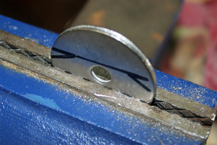
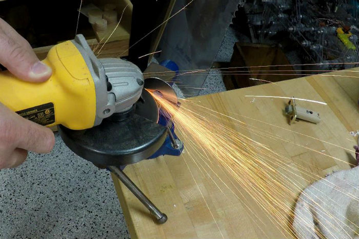
Cut two 2” washers in half using an angle grinder, creating the three portions to insert in the base, plus a spare. Cut the two 1-1/2” washers similarly, angling your cuts to preserve a small portion of the inner hole so that it can hang from the ¼” bolt. Knock off any burrs with a file or rotary tool.
How to Wire a Variable Capacitor
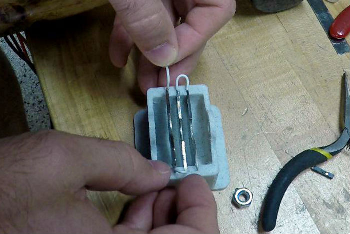
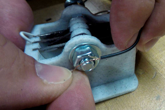
- Take a piece of wire 1” to 1-1/2” long and strip back a quarter of an inch of wire on each side. Insert the stripped portion into the groove for the first washer. Push this washer in, locking the wire down, then place the other stripped end into the adjacent groove.
- On the other side of this groove, insert another similarly stripped wire, then lock both down with a second washer section.
- Do the same on the third washer, using a longer piece of wire on the final insertion. You’ll hook this wire up to external equipment.
- Test your capacitor with a voltmeter to see if the wires and washers are electrically continuous.
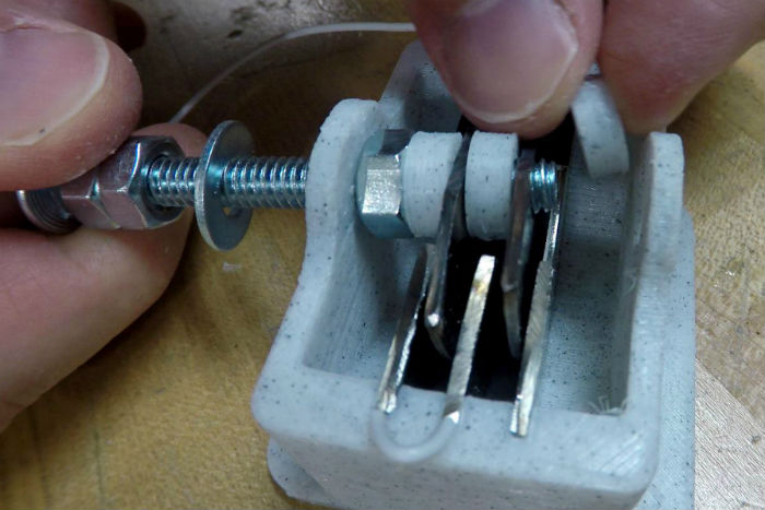
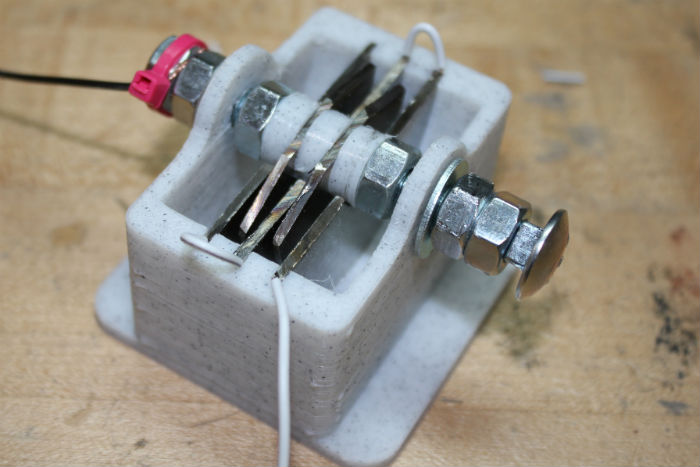
- Thread the bolt in as shown in the above images. Spacers will separate the two 1-1/2” lobes, and be sure to tighten the nuts on either side to keep them in place.
- Push down on the lobes while tightening to maintain good electrical contact with the bolt. Properly space the nuts on the outside of the base, then lock them to each other to keep the middle assembly in place. The small washers allow everything to rotate smoothly.
- Before locking down the nuts opposite the bolt head on the base, place a second wire in a position where you will clamp it between the two. This creates a second electrical contact for the new capacitor.
- Wrap a zip-tie around the wire and nuts to act as a strain relief.
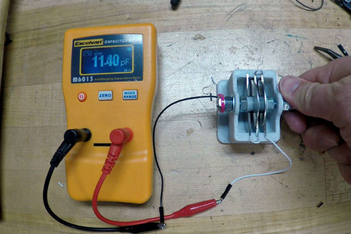
- Test the capacitance between the two leads to this device.
You should see it vary from somewhere around 5 to 15 pF. Your body will change the device’s capacitance, so set it as desired, then measure the device after removing your fingers.
Adding Capacitance to your Variable/Tuning Capacitor
If your application requires more capacitance, you may be able to achieve it by adding more washer lobes or decreasing the space between them. In this scenario, add paper or another solid dielectric to prevent each lobe from touching if needed. If you add a plastic insulating cap to the tuning bolt, you’ll dramatically reduce the effect your fingers have on capacitance readings.