There is an infinite amount of ways to connect electronic devices or power sources. Whether supplying power, data, or other kinds of signals, a designer has many options to choose from with regard to specifying connectors, pinouts, and cable assemblies. But often, it’s not so simple. There are many factors involved in making sure the right cable is selected (or designed) for a given application — things like environmental factors, current-carrying capacity, voltage ratings, size constraints, performance/speed, bend radius and other mechanical considerations, and finding the right balance between cost, quality, and capability.
What’s more, engineers may also find themselves wearing multiple hats — mechanical engineers doing some electrical design work and vice versa. Whose job is it typically to design a custom cable? What’s the process behind it and how can the designer incorporate features to provide a reliable, application-appropriate cable assembly while keeping it cost-effective and manufacturable?
Let’s quickly review the basics of a typical cable assembly:
· Brings power or data from one endpoint to another (or multiple)
· Bundles one or more wires together carrying current
· Has some sort of insulation to protect the wires from the outside environment
The application will often drive the following considerations:
· Current capacity
· Voltage rating
· Length
· Conductor count
· Termination (plug, soldered wire, etc.)
· Mechanical constraints
· Speed and performance constraints
· Environmental constraints
· Anything application-specific such as safety or high-reliability, ultra-compact systems, ease of use, or cost-sensitive/mass-produced products
Where to begin?
When faced with the need to electrically connect something together, the best place to start is with the power requirements, as that should help drastically narrow down the variety of cables and plugs to choose from.
Let’s begin with current. Figure 1 is a table that shows many columns related to wire specifications, but for this discussion, let’s focus on the “AWG,” “Ohms per 1000 ft,” and “Maximum amps for chassis wiring.”
American Wire Gauge (AWG) is a standardized set of specifications that allow for different sizes (diameter) of wire to carry more or less current. The thicker the wire (more copper), the more current it can carry. A 24 AWG wire, for instance, is rated at 3.5 A for normal wiring (by itself and not bundled with many other wires). It’s also worth considering that with longer wire comes added resistance. A 24 AWG wire will have about 25 Ω per 1,000 feet. It may not seem like a lot, but even 2.5 Ω for 100 feet, for example, may introduce significant voltage drop on a sensitive signal or power rail, depending on how much current is being carried. So length and current capacity should both be taken into consideration when specifying a cable.

Figure 1: Wire specification table for American Wire Gauges
Voltage ratings (and type) can be just as important. For normal AC wall voltage, there are typically safety standards that must be met, and these standards relate to the wire’s insulation, often requiring special material such as PVC. Depending on the application, there should be special considerations with regard to these insulations and how the wires are routed in the system (enough clearance from other nearby cables, including low-voltage DC).
While it usually makes sense to spec a cable with a specific or exact conductor count that is needed for an application, having extra conductors may benefit the design and open up the possibility for future signal additions. Also, when using multiple cables with the same terminations/connectors, it’s usually best to have as much variety as possible so that it makes assembly easier and less prone to error (miswiring).
Cables are generally terminated with connectors but may include other forms of termination, such as wires soldered directly to a PCB/component or pogo-pin plugs meant for temporary interfaces, generally used for programming or testing. Connectors can make all the difference with regard to user-friendliness and robustness/security. Things like keyed connectors for one-way installation and locking mechanisms to keep them secure, tabs to help pop plugs out of their sockets, and even having quick/easy crimps associated with the connector can make both the manufacturing process and user operation much easier to work with.
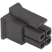
Molex’s MicroFit 3-mm series (shown in Figure 2) is a common example of a connector that has one-way installation and a locking tab.

Figure 2: Molex MicroFit 3-mm series connector containing one-way installation and locking tab
Mechanical Design Considerations
One major part of specifying a cable is the mechanical design consideration. All cables have a bend radius, the minimum radius that the cable must meet to stay below stress or strain ratings of the bundled wire. Flex cable assemblies are prone to ripping and tearing when these bend radii are not met, so the next time you work with an LCD or motor encoder assembly, pay close attention to this.
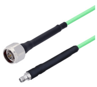
Along the same lines, strain relief in general is something to consider for cables that are used frequently or see a lot of handling by the user. While many off-the-shelf assemblies have this, it’s usually best to include this in custom cable designs as well. Even something as simple as adding heat-shrink tubing around the connector, crimped area, and portion of the cable (shown in Figure 3) can make a huge difference with reliability.

Figure 3: N male to SMA female cable with heat shrink for added strain relief
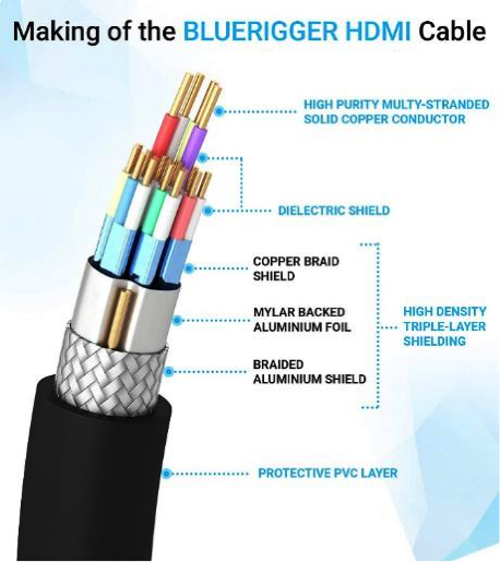
When performance is a key requirement (generally speed-based), then other considerations should be made as well. Most high-performance cabling comes with shielding to reduce both emitted radiation and susceptibility to radiation, and differential wires may be braided together and insulated from other nearby wires. Figure 4 shows an assembly of an HDMI cable by Bluerigger containing three levels of shielding.

Figure 4: HDMI cable assembly by Bluerigger
If harsh conditions exist such as heat, moisture, shock, and exposure to chemicals, specific materials may need to be specified throughout the entire assembly, including conductors, insulation/jacket, shielding, and additional water-/flame-blocking components. Generally, it’s best to get off-the-shelf cabling (or at least a vendor that specializes in custom assemblies for extreme environments) that has been certified and tested for harsh conditions. Industries such as aerospace, oil/gas, marine, and military usually see these kinds of conditions.
Should You Go with Off-the-Shelf Components?
While on the subject of off-the-shelf cable assemblies, let’s take a second to discuss. When should a designer choose an off-the-shelf, pre-made, pre-defined cable assembly in their application? Is it cheaper than specifying a custom cable and managing its production? In general, yes. However, many advantages can be gained from having custom cable assemblies controlled by the designer, including custom lengths, which may make mechanical routing and assembly easier; controlled material and connector selection; properly rated materials throughout the assembly; and overall more flexibility if things need to change in the future. And in many cases, a designer may not even have a choice, such as a fan or motor assembly that is provided with flying leads. Sometimes, a vendor will custom-terminate an assembly such as a battery or motor, but it’s often the designer that must incorporate peripheral components into a custom cable.
On the other hand, off-the-shelf cables may help with time to market, ease of assembly, familiarity with common connections, easier sourcing and procurement of cable assemblies, and lowering risk for applications requiring high levels of safety and reliability (and harsh environments). One strike against off-the-shelf cables: obsolescence management. When a vendor decides to stop producing a cable, it’s like any other obsolescence dilemma with regard to electronics — there’s risk of major design changes to meet new cable connectors/footprints.
So the answer is, unfortunately, a recurring theme: It depends on the application.
Should You Go with a Custom Design Solution?
For cables that are custom-designed, there is a slew of software packages equipped to handle everything from simple, one- or two-wire cable bundles to monster, multi-endpoint, shielded, braided, insulated assemblies for the most complex systems.
Solidworks, a common mechanical design suite, has an electrical add-on suite (Solidworks Electrical) that includes cable design features, allowing an electrical engineer to define PCB connections and pinouts and then build cable drawings and system diagrams based off of those connections (see Figure 5). In addition, it gels with the mechanical portion of the program by allowing full visualization and planning for wire routing in the system. This greatly reduces the risk of iterations of cable drawings while optimizing length and routing features. Zuken E3 is another popular cable design package that is packed with ready-to-go libraries for cable drawings and system diagrams.

Figure 5: Solidworks Electrical 3D routing visualization of many cable/wire assemblies built directly from system diagram and cable drawings
But high-end software isn’t always the answer. Even something as simple as Microsoft Visio can be used to produce decent cable drawings. Figure 6 is an example of a basic, custom-designed cable drawing that includes the following:
· Construction drawing demonstrating clear visualization of assembly
· Detailed end-to-end pinout
· Dimensions of cable length and location of heat shrink and internal solder connection
· Bill of materials with part numbers
· Assembly notes
· Revision table and header block
The cable should be entirely manufacturable, based on this one-page drawing:

Figure 6
And whose job is it typically to design these? It all depends on resource allocation for a given company and the bandwidth of the engineers. Generally, it’s ideal to have electrical engineers specify the cable, but the actual drawing can be done by anyone.
Conclusion
To conclude, there are many things to consider when specifying a cable for a system. Pros and cons exist for off-the-shelf assemblies and custom designs, and powerful software and toolsets provide designers with a quick, low-risk path to market.
Don’t be afraid to draw up a cable design and look into the cost for custom assembly; it’s not as painful as you might think and will ultimately give the designer more control over the system design in the long run.


