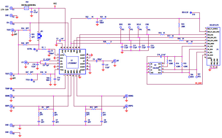
DC2391A, Demo Board based on LTC5589 700MHz to 6000MHz Low-Power I/Q Modulator
Using Part
Vignette
1 / 1
Documents connexes
Pour les produits finaux
- Battery Powered Systems
- Military Radios
- Modulators
- Software Defined Radio
Description
- DC2391A, Demonstration Circuit is optimized for evaluation of the LTC5589 low power I/Q modulator up to 4.5GHz. For frequencies above 4.5GHz, LO matching circuit on the DC2391A demo board can be easily modified for improved image rejection performance. The four balanced I- and Q-baseband input ports can be either AC-coupled with internal bias supplied, or DC-coupled from a source with a common-mode voltage level of about +1.4V. The SPI interface is used to set internal registers which control the gain, optimum center frequency, I-offset, Q-offset and sideband suppression
Caractéristiques principales
-
Operating Frequency700 to 6000 MHz
Pièces en vedette (2)
| Pièce numéro | Fabricant | Type | Description | |||
|---|---|---|---|---|---|---|
|
|
24LC025-I/ST | Microchip Technology | EEPROM | EEPROM Serial-I2C 2K-bit 256 x 8 3.3V/5V 8-Pin TSSOP Tube | Ajouter au panier | |
|
|
LTC5589IUF#PBF | Analog Devices | RF Modulators/Demodulators | Quadrature Mod 6GHz 24-Pin QFN EP Tube | Ajouter au panier | |


